Article sections
The RADIX LI Wing Kit is a flight control system designed for airplanes / wings. With its compact form factor, it is ideally suited for small airplanes. The RADIX LI flight controller runs our version of iNav with the BrainFPV graphical (vector based) on-screen display (OSD) and the RADI LI Wing Power Board (wPB) features highly accurate current sensing making it the perfect choice for long range airplanes with low current draw. The BrainFPV GPS provides positioning information and enables autonomous features like return-to-home, loiter, cruise, etc. The OSD also uses the GPS data to indicate the home direction, ground speed, a map, and more.
The RADIX LI Wing Kit consists of the following components:
- RADIX LI Flight Controller (FC)
- RADIX LI Wing Power Board (wPB)
- BrainFPV GPS
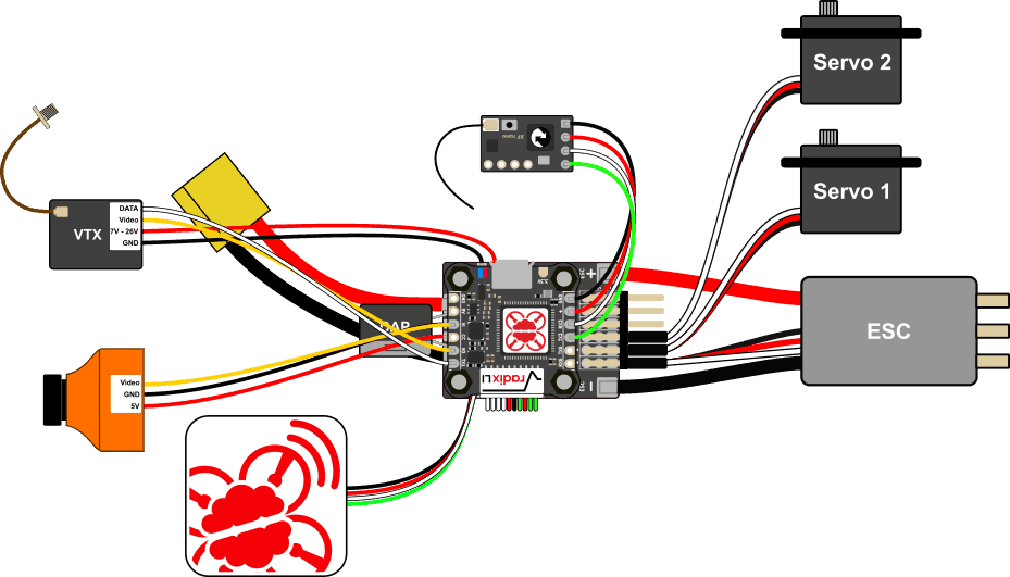
Below, we will walk you through setting up the different components and how to connect them to your other components, i.e., RC receiver, FPV camera, video transmitter, servos, and motor.
Install Servo Headers
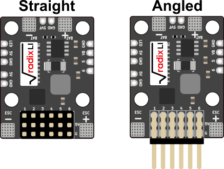
The wPB can be used with either straight or angled servo headers. Both are included with the wPB. Use whatever works best for the airplane you are building. To install the servo headers, put them in place and solder the pins on the bottom of the wPB.
Powering Servos
Servos on fixed wing aircraft can draw quite a lot of current. The RADIX LI wPB has a 3A, 5V regulator, which is enough for powering small servos. As a reference, the servos on a Nano Talon can be considered small and can be powered by the wPB, while the ones on a TBS Caipirinha 2 are too power hungry to be powered by the wPB.
To power the servos, you have 3 options:
- Power servos from the wPB: Simple, but only works for small servos.
- Power them from the ESC: Simple, servo size depends on ESC BEC.
- Power them from a separate BEC: Most reliable solution, servos still work if ESC fails.
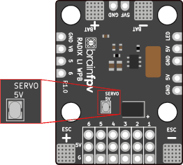
If you decide to power the servos using the wPB, use your soldering iron to bridge the “SERVO 5V” jumper on the bottom of the wPB.
Connect Battery, ESC, and Capacitor
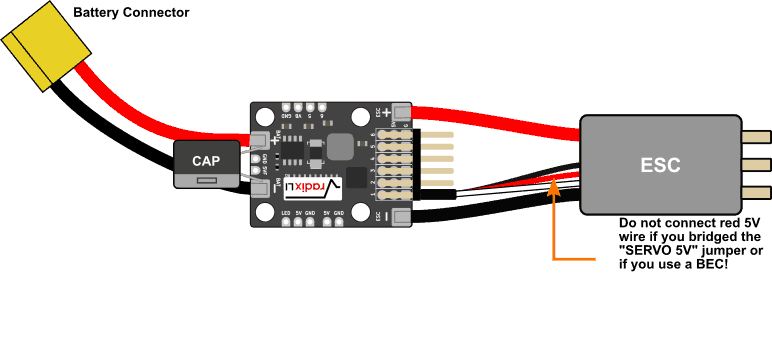
Connect the cable for the battery and the ESC (motor controller) as shown below. The wire gauge that should be used depends on your aircraft. For a small wing that draws less than 20A, you will be fine with 18 AWG, whereas for a very powerful wing you may want to use 12 AWG. The best bet is to use whatever your ESC comes with.
The RADIX LI wPB also includes a capacitor (“CAP”) that helps with reducing motor and ESC noise. Depending on how you power your video transmitter and FPV camera and on how good their noise filtering is, you may not need the capacitor. If you decide to install the capacitor, solder it in parallel with the battery, as shown below. Pay attention to the polarity of the capacitor; the band indicates the negative side that needs to be connected to “BAT -“.
Connect Servos
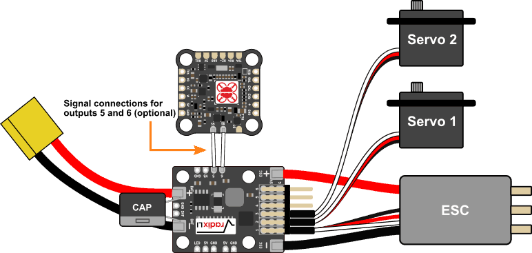
Servos are used to move the control surfaces of your aircraft. How many you need depends on your aircraft; For a flying wing you only need 2 servos, whereas for a aircraft with aileron, elevator, and rudder, you may need 3 or 4.
The RADIX LI wPB has servo headers for 1 motor and 5 servos. The signals to control the motor and the first 3 servos (outputs 1 to 4 on the servo header) are supplied by the flight controller via the 10-pin cable that connect the RADIX LI wPB to the RADIX LI FC. If you need more than 4 outputs total, use the included wire to connect the pads marked 5 and 6 to the S5 and S6 pads of the RADIX LI FC.
Connect BrainFPV GPS
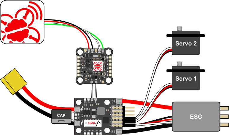
The BrainFPV GPS provides positioning information to the RADIX LI flight controller, enabling autonomous modes such as return-to-home, position hold, and waypoint navigation. The recommended way to connect the GPS is UART4 using the pads on the bottom of the RADIX LI as shown below.
Notice that the white TX wire of the GPS needs to be connected to RX4 and the green RX wire to TX4. Crossing the wires makes sense considering that TX stands for “transmit data” and RX for “receive data”, so the GPS sends data out on its TX wire which is then received by the RADIX LI on its RX pad and vice versa.
Connect Camera and Video Transmitter
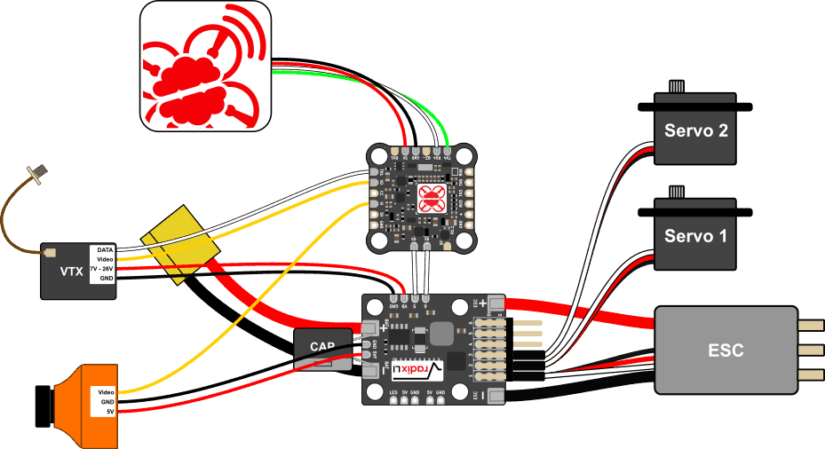
Video transmitters (VTX) consume a lot of power and so do combined HD/FPV cameras, so they need to be powered from the RADIX LI wPB. The wPB has a filtered 5V output (“5VF”) that can supply up to 1 A, as well a a “VB” output that supplies battery voltage. Depending on your VTX and camera, you need to either power them from 5V or from the battery voltage.
Camera: Connect the GND and 5V wires of the camera to the GND and 5VF pads at the front of the wPB. In order for the RADIX LI to overlay the on-screen display (OSD) onto the video, the video output of the camera needs to be connected to the RADIX LI. To do so, connect the yellow video wire from the camera to the video input (VI) pad of the RADIX LI.
Video Transmitter: Here we assume that your VTX is a “high voltage” (HV) video transmitter that can be powered from battery voltage. To do so, connect the GND and power wires to the GND and VB pad of the wPB. The VTX transmits the video signal coming from the RADIX LI, so the yellow video input wire needs to be connected to the video output (VO) pad of the RADIX LI. Most video transmitters can also be controlled by the flight controller using a digital protocol, such as TBS SmartAudio. If your VTX supports this feature, connect the data input of the VTX to the TX1 pad of the RADIX LI.
Optional: Programmable RGB LED’s and Buzzer
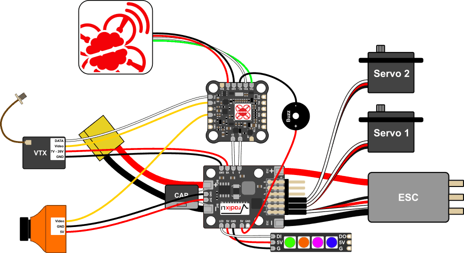
The RADIX LI flight controller can control programmable RGB LED’s, which are bright LED’s that can be used to differentiate pilots by color in a race, blink in different colors, etc. In short, they make your wing look cool and help other pilots to better see you, especially at night. It also has support for a buzzer that can be activated using a switch on your RC transmitter. Buzzers are very useful for locating your plane when you unintentionally land in a corn field or forest ;).
RGB LED’s: The LED’s are wired as shown below. Any LED strip with WS2812B compatible RGB LED’s will work. The LED strip will have a data input (DI) which is connected to the LED output of the RADIX wpB. Naturally, you also need to connect ground (GND) and 5V. Note that the LED strip will also have a data output (DO), which allows you to daisy-chain LED strip together, i.e., you can connect the DI of a second LED strip to the DO of the first strip, and so on.
The firmware supports up to 32 LED’s. When connecting LED’s, keep in mind that each LED consumes about 50 mA (0.05 A) of current, so if you use a 32 LED’s, it will draw 1.6 A from the 5V supply for the LED’s alone. The 5V regulator of the wPB supports up to 3A, so you will only have 1.4 A left for other 5V devices, such as the camera and servos. It is therefore advised to use a separate 5V regulator for the LED’s if you want to power a lot of them, especially if you also power the servos from the 5V regulator of the wPB.
Buzzer: You can use any DC (direct current) 5V buzzer with the RADIX LI FC / wpB. The current drawn by the buzzer should be less than 200mA, which should be the case for pretty much every buzzer sold for RC. Wire the negative pad of the buzzer to the BZ- pad of the RADIX LI FC and the positive pad to a any 5V pad, e.g., the 5V pad next to the LED output of the wPB, as shown below.
Stack RADIX LI FC on top of RADIX wPB
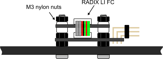
The RADIX LI FC and the RADIX LI wPB are designed to be stacked together. Use the wire included with the RADIX wPB to connect them together and use M3 screws and nylon nuts to mount the the FC on top of the wPB. Make sure that you use one nylon nut on top of the wPB and one underneath it to ensure adequate spacing and airflow. Do not mount the RADIX wPB to your airplane using double sided tape only, as the shunt resistor for current measurement on the bottom of the wPB needs airflow for cooling.
Connect RC Receiver
To complete the wiring, we connect the RC receiver. The RADIX LI can be used with a large number of different RC receivers. Pretty much any “single wire” receiver, i.e., serial or PPM (Pulse Position Modulation) is supported. In the diagram below, a Crossfire Nano Rx is connected to the RADIX LI flight controller. To power the receiver, the GND of the receiver is connected to the GND of the RADIX LI FC, and the 5V input is connected to the “+” pad next to it. Note that the “+” is a special 5V pad that is also powered from USB. It has limited current handling capacity and is only intended for powering an RC receiver. Do not power other components from it or use it power an RC receiver with a backup battery (such as the Crossfire Diversity Nano Rx). Doing so will damage the RADIX LI FC.
The signal wires of the RC receiver are connected to RX3 and TX3 of the RADIX LI FC. For all other supported receiver types, refer to the RADIX manual; The wiring is the same as for the RADIX FC.
Software (iNav)
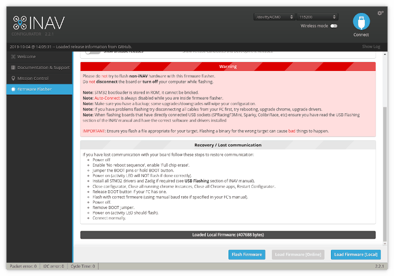
When used for airplanes, the RADIX LI flight controller uses a custom version of iNav with extra graphical OSD features. To install it on your RADIX LI, download the iNav Configurator, as well as the firmware (hex file) from the BrainFPV iNav release page. After that, start the iNav Configureator and under Firmware Flasher, click on “Load Firmware [Local]” and open the downloaded hex file. Then click on “Flash Firmware”. If you have problems flashing it, please see here.
This guide currently does not cover how to configure iNav for your airplane. Please follow the official iNav Fixed Wing Guide. Another good resource is the Painless360 video series for iNav 2.1.
The RADIX LI is configured like other iNav flight controllers. Some differences and things to keep in mind are:
- The RADIX LI only supports one motor output (Output 1)
- Some extra OSD features need to be configured in the OSD menu (access it using your RC transmitter sticks). See here for more information about the OSD features.
- The current sensor scale (under Configuration) needs to be set to 500 (50 mV/A) for the current sensing with the RADIX LI wPB to be correct.

