Article sections

ArduPilot is an advanced, open source, autopilot software. It supports multirotors, airplanes, and other vehicles, such as, rovers and VTOL aircraft. The RADIX 2 HD is the first flight controller by BrainFPV that is officially supported by ArduPilot starting with release 4.4.1 in fall 2023. Below are links to resources on how to use ArduPilot in general and specific instructions for the RADIX 2 HD.
ArduPilot Resources
- The ArduPilot website has excellent documentation.
- The ArduPilot Discourse forum is great for support. Note that release announcements are also posted there.
- There is an ArduPilot Discord server for real-time chat. Make sure to read the rules before posting. It is mostly used for development and not user support.
- The source code can be found on GitHub.
There are also a number of videos on how to get started with ArduPilot. Perhaps unsurprisingly, the best ones are by Painless360.
The “Pixhawk 2023 Series” is an excellent introduction on how to use ArduPilot. The video series focuses on multirotors, but many steps are the same for other vehicle types. Note that the RADIX 2 HD uses the BrainFPV Bootloader. So, you will need to flash it differently. See below for more information.
RADIX 2 HD Specific Information
Information about the serial ports, PWM outputs, etc. supported by the RADIX 2 HD can be found on the ArduPilot WIKI page.
Installing ArduPilot on your RADIX 2 HD
The RADIX 2 HD uses a custom BrainFPV bootloader. To install firmware on it, simply copy the firmware file to the USB drive that appears when the flight controller is connected to your computer. See here for more information. To install ArduPilot on it, head to the Firmware page, select ArduPilot, the vehicle type (Copter for multirotors, Plane for airplanes, Rover for rovers) and the version and then click on Download.
After downloading the file, connect your RADIX 2 HD to your computer with the BOOT button pressed and it will show up as a USB drive. Copy the downloaded firmware file to it. Once the copying finishes (the green LED stops blinking fast), safely remove the drive. At this point, the RADIX 2 HD will reboot into ArduPilot. Note the following:
- ArduPilot needs a Mirco SD card inserted into the RADIX 2 HD. Without it, it will not run.
- When running a new version of ArduPilot the first time, the green LED will stay on for several seconds before the firmware starts running. This does not happen in subsequent boots. In case you are wondering why: This is because the bootloader copies parts of the firmware to different parts of the external flash chip, from where it is then executed.
Note that the RGB LED of the RADIX 2 HD shows the ArduPilot status. Detailed information on what the colors and blink codes mean can be found here.
EMI Suppression for GPS and Receiver
The RADIX 2 HD has 1 MB of RAM but limited internal flash memory, which is used for the bootloader. Firmwares like Betaflight and INAV have modest memory requirements and are executed from RAM. ArduPilot on the other hand needs much more memory. So, some of the ArduPilot code is executed from the external flash chip of the RADIX 2 HD, which is connected to its STM32 H7 microcontroller by a Quad SPI interface running at 120 MHz. We have found that the Quad SPI signals generate additional electromagnetic interference (EMI), which negatively affects GPS performance and may also affect RC receivers. In order to reduce the EMI effects, we recommend the following:
- Make sure the GPS, RC receiver, and telemetry modules are at least 10 cm away from the RADIX 2 HD.
- For GPS, we recommend adding a ferrite ring to the ground and 5 V wires that connect the GPS to the RADIX 2 HD. See below for more details. Note that we have found that this is not needed for 915 MHz RC systems, such as TBS crossfire, and 2.4 GHz systems, such as TBS Tracer and ExpressLRS.
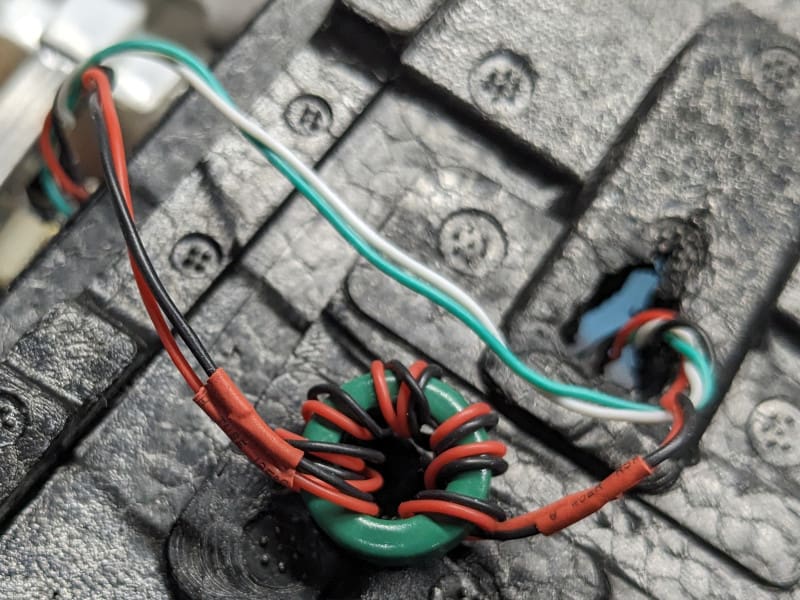
The photo below shows a ferrite ring with an outer diameter of 10 mm installed between the RADIX 2 HD and the GPS. We recommend winding both the ground and the 5 V signal through the ring with a total of about 7 windings and some separation between the input and the output.


